An attempt at solving a challenge posed by Max Shirokawa here:
Littrow Grating Problem Google Doc
New to Exact Constraint? Check out a quick intro here:
Make Parts Fit Right the First Time with Exact Constraint Analysis
Problem Setup & Assumptions
Let’s set up two coordinate systems, one aligned to the laser (XYZ) and one embedded in the face of the grating (ABC):
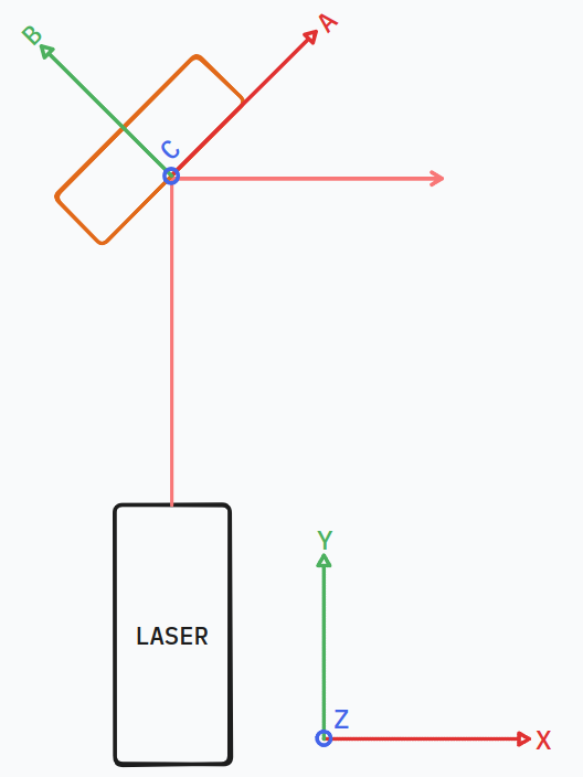
We’ll assume the laser light is coming in aligned in the YZ plane and collimated such that it can be treated as a ray.
Motion Constraints
Translating the desired degrees of freedom into rotations on the ABC coordinate frame, the desired movement and control is:
- RC
- Coarse alignment with 100 TPI screw
- Fine alignment with piezo actuator
- 1-3 deg range of motion
- Pre-set to 44 deg
- RA
- 1-5 deg range of motion
- Pre-set to 0 deg
- Adjustable, then fixable in place
All other degrees of freedom should be constrained (RB, TA, TB, TC).
Constraints and Degrees of Freedom
Let’s sketch up the grating with the desired degrees of freedom RA and RC:
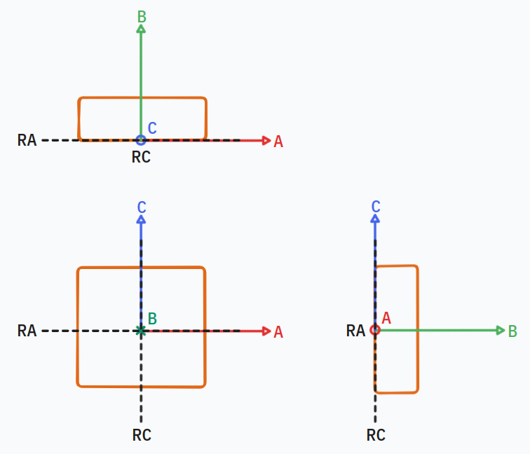
From exact constraint analysis, we know that:
Degrees of freedom + constraints = total degrees of freedom
In 3D, we have 6 total degrees of freedom (three translation, three rotation), so we need to place four constraints to have the two rotational degrees of freedom desired.
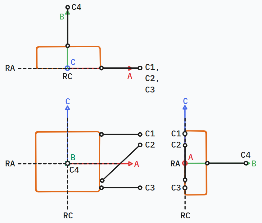
We know that intersecting constraints create an instant centre of rotation, so all four of our constraints need to intersect the desired degrees of freedom.
Placing Constraints
One way to accomplish this is to lay 3 constraints in the AC plane to form a sheet flexure, then place the fourth constraint at the intersection of RA and RC.
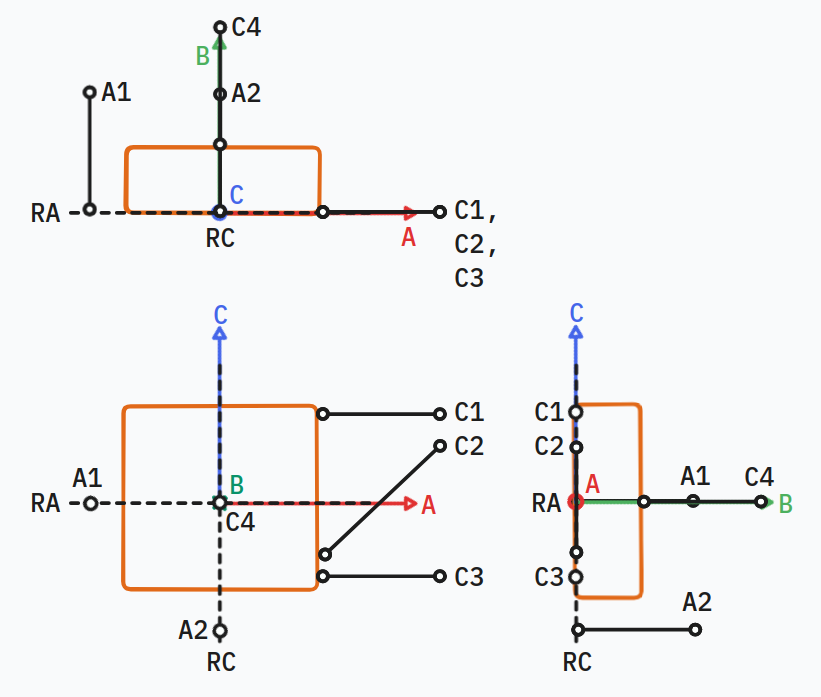
We can then put in the adjustment mechanisms as constraints marked as A1 and A2 to provide the adjustments of RA and RC:
Nesting Forces
If C4, A1, and A2 are contact constraints like the tip of a screw or piezo actuator, we’ll need a nesting force to keep the grating in contact with those constraints. We can place a single nesting force in the triangle between A1, A2, and C4, and ideally roughly equidistant to the three constraints to keep them in contact.
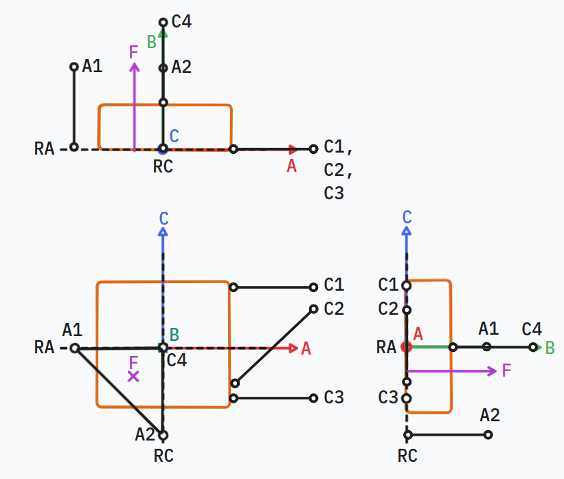
Design Attempt One
Designing for Prototyping
As is always the case, the simple and elegant exactly constrained model needs a little adjustment to be manufacturable.
Max mentioned having access to a 3D printer, so let’s design for manufacture using the printer. We can design in easily available high-precision components like ball bearings and pins for contact constraints.
Mounting Sketch
I sketched out a first concept on the design:
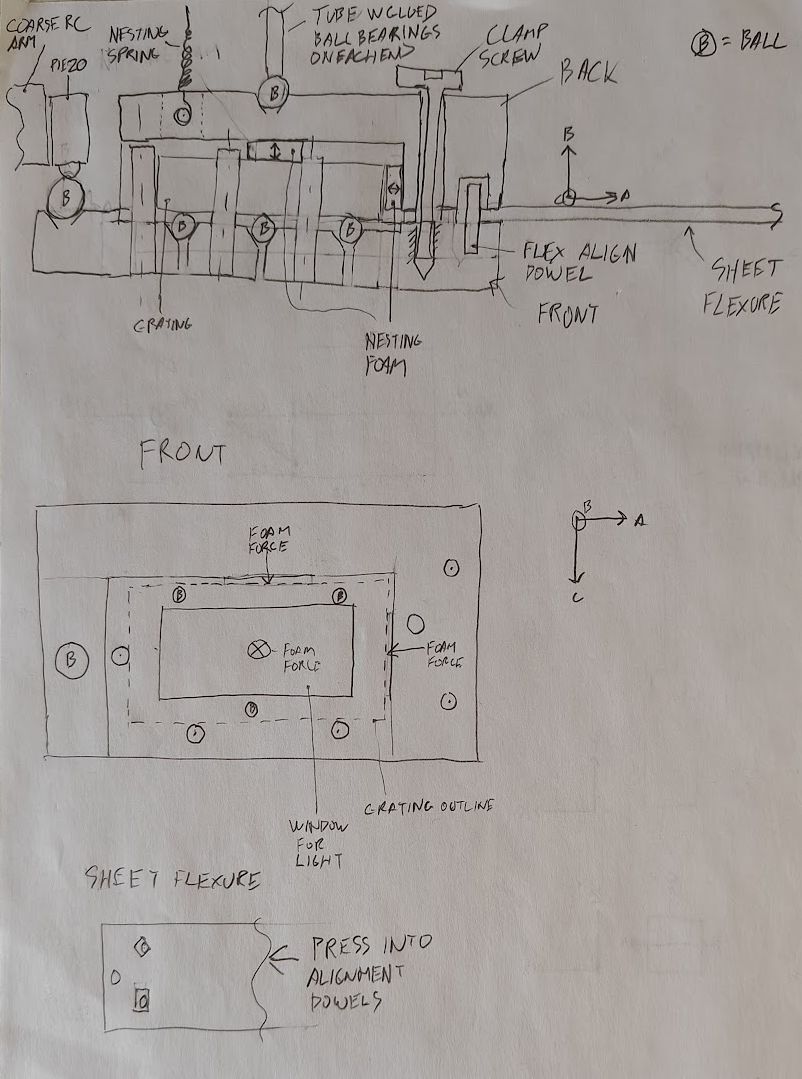
It locates the grating on an exactly constrained three-ball and three-pin mount, with foam pieces on the back and side to nest the grating into the constraints. The grating is then held by a two-part 3D printed mounting mechanism to keep everything in place.
The design uses a laser- or waterjet-cut sheet metal flexure that aligns to the mounting mechanism with dowels.
The back mounting block has a hole with a cross-pin to hold the spring in place.
Not sketched in is the base that holds the other side of the flexure, or the adjustment screws.
A decent first thought, but I can simplify things and clarify the design by moving to CAD.
Design Attempt Two - WIP
Check out the WIP CAD in Onshape!
Key features:
- Single print mounting block and flexure with built-in constraint contact surfaces instead of separate parts
- Exactly constrained base that hangs from the mounting rails
- Individually adjustable and independent degrees of freedom
- Single tension band to keep grating in place